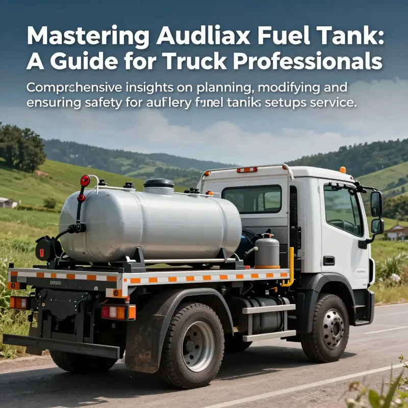
Mounting an auxiliary fuel tank on a service truck is a significant yet crucial upgrade that extends driving range and enhances operational efficiency. This guide addresses the pivotal steps involved—from meticulous system design and planning to the technical intricacies of fuel system modifications, down to adhering to safety regulations and compliance. Each section aims to equip long-haul truck drivers, trucking company owners, fleet managers, and maintenance specialists with a thorough understanding of the complete process, ultimately ensuring a secure and efficient addition to their vehicles.
Blueprints in Motion: Systematic Design and Planning for an Auxiliary Fuel Tank on a Service Truck
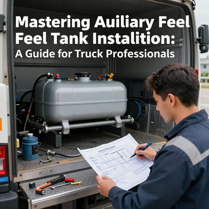
The decision to mount an auxiliary fuel tank on a service truck begins long before the first bolt is tightened. It starts with a careful mental map of how a vehicle carries its lifeblood—its fuel—through a demanding workday, across uneven surfaces, and in a fleet ecosystem where uptime matters as much as payload. A well-planned design is not merely a count of gallons added to the chassis; it is a disciplined negotiation between capacity, safety, and the truck’s existing architecture. To approach this task with clarity, the designer must first translate operational needs into a tangible system that sits within the constraints of the vehicle and the rules that govern fuel systems. The result is a living blueprint that integrates structural realities, fluid dynamics, and human factors into a cohesive whole. In that spirit, the chapter that follows threads together the core principles of system design and planning, offering a narrative of how to think, not just what to do. It treats the auxiliary tank not as a separate add-on, but as an extension of the truck’s purpose: to extend range without compromising safety or reliability.
The central question in this design exercise is balance. The auxiliary tank must be large enough to deliver meaningful range extension, yet compact enough to avoid overwhelming the truck’s chassis, aggravating weight distribution, or reducing ground clearance. It must be compatible with the main fuel system, but it cannot simply piggyback on it; instead, it must become a careful, controlled branch that preserves the integrity of pressure, flow, and containment. In practice, that balance starts with capacity planning. Industry guidance typically anchors auxiliary tanks around a maximum range of roughly 24 gallons (about 100 liters). This ceiling is not arbitrary; it reflects a convergence of material science, safety margins, and the realities of vehicle codes. An appropriately sized tank is constructed from materials chosen for durability and compatibility with diesel or gasoline fuels, with HDPE and reinforced steel as common options depending on duty cycle, chemical exposure, and environmental conditions. The material choice is not cosmetic; it informs everything from corrosion resistance to fuel slosh behavior in transit, and it sets the stage for a robust sealing strategy beneath the hood and behind the scenes of the truck’s undercarriage.
Beyond capacity, the placement of the auxiliary reservoir matters as much as the tank itself. The location must preserve the vehicle’s structural integrity while maintaining a favorable center of gravity. If the tank sits too low or too far aft, it can invite handling quirks, especially during quick maneuvers, emergency stops, or traversing washboard roads. The decision may wind up near the chassis’s underbody, in a recessed bed niche, or in a dedicated enclosure that keeps the tank shielded from road debris while remaining accessible for maintenance. Each option has tradeoffs. Under-chassis mounting can suffer from exposure to moisture and impacts, but it often minimizes interference with the cargo area. Bed-mounted configurations maximize space for equipment but can complicate loading and service access. A dedicated compartment can offer the cleanest integration, but it requires careful fabrication and sealing of all penetrations entering the vehicle’s fuel path.
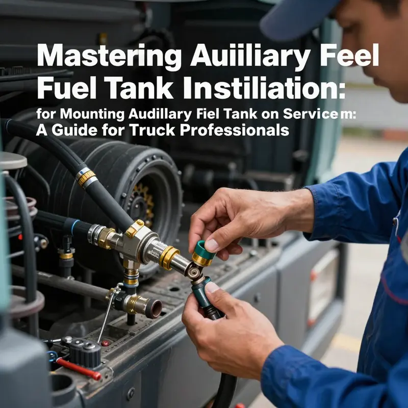
A clear risk in any dual-fuel arrangement is interference with fuel flow. The auxiliary system must feed the engine in a controlled, predictable manner, without creating backpressure or vapor lock on the main line. The guiding principle here is a direct, low-stress inlet from the auxiliary tank to the main line, with a dedicated feeding path that does not require sharp bends or unnecessary long runs. The goal is to minimize potential bottlenecks, kinks, and leak points. The engine’s fuel supply usually continues to be managed by the primary pump, but a secondary, reliable transfer path is essential for the auxiliary tank to be truly functional under load. A common engineering approach is to connect the auxiliary tank’s outlet back into the main line through a robust, purpose-built connection that avoids repeated bending that could become fatigue points. In practice, this means using a high-quality T-connector and a carefully chosen set of hoses and fittings rated for fuel exposure, with all seams and joints sealed to prevent drips and vapors. A well-designed system will also incorporate separation of automatic and manual control modes, so the driver can select between continuous automatic feeding and a conscious, manual handover when needed. This is not merely a convenience feature; it is a safety mechanism that lets the operator control fuel delivery in dynamic conditions, reducing the likelihood of unintended fuel transfer or pressure spikes.
In discussing system design and planning, one cannot ignore the regulatory scaffolding that surrounds any fuel-tank modification. Regulations exist to ensure that fuel systems remain predictable, fire-safe, and environmentally responsible. The design must align with applicable road-vehicle standards, emissions considerations, and safety testing protocols. A rigorous sealing test follows construction, often involving a controlled water fill and a pressurization step that simulates operation conditions to reveal leaks. The test is not simply a procedure; it is a proof of the system’s integrity under the vibrational, thermal, and pressure cycles that occur when the vehicle is in service. Adherence to standards is not optional theater; it is the backbone that guards against catastrophic failures in the field. In many jurisdictions, the modification requires formal approval before installation and annual inspections that specifically address the fuel system and its emissions implications. Industry practitioners emphasize professional certification; the complexity and risk of fuel-system work warrants the involvement of qualified technicians with the appropriate credentials. This is not a DIY upgrade but a calibrated integration, where the robot-like precision of engineers must sit beside the craft and judgment of repair professionals.
The safety features embedded in a well-planned system complete the triad of capacity, placement, and regulation. A recessed fuel-filler cap with a safety vent, for example, helps prevent leaks and spills during motion and in gravity-driven slope scenarios. Integrated baffles within the tank dampen fuel slosh, reducing surge forces that might affect vehicle control, especially when the truck is loaded with equipment and operators. Grounding and bonding are essential to prevent static discharge that could ignite fuel vapors in the presence of heat or a spark. A check valve or anti-siphon mechanism at the filler neck further guards against siphoning and vapor mixing, mitigating both safety and environmental risks. These features are not cosmetic add-ons; they are essential design elements that harmonize with the vehicle’s electrical system, the operator’s workflow, and the fleet’s safety culture. They also reflect a broader learning from the field: that fuel-system integrity is as much about preventing failure as it is about enabling performance.
The planning phase must also anticipate maintenance realities. Inline electric fuel pumps, often favored for retrofit applications, offer durability and serviceability, but they demand access, filter integration, and a minimal number of failure points. The design should grant easy access to inspection ports and components that are subject to wear. This practicality matters not only for routine servicing but also for emergency repair in the field, where a nonessential component could become a bottleneck. In the same spirit, the system should be designed for inspection by non-specialists when needed, with clear labeling and safe, accessible points for checking hose connections and clamps. The human factors dimension—how technicians and operators interact with the system—should guide the layout. For example, the proximity of the auxiliary line to the engine’s heat source, the routing of cables, and the ease of isolation in case of a leak all contribute to safer operation and faster maintenance.
Material selection, too, carries implications beyond immediate function. The environment in which a service truck operates—urban streets, rural backroads, or rugged worksites—dictates corrosion resistance, UV tolerance, and the potential for abrasion. The design should factor in these environmental variables and select materials that maintain their integrity under vibration, thermal cycles, and exposure to fuel. In addition, the environmental footprint of the system is increasingly a design criterion. Minimizing evaporation losses, preventing spills, and ensuring fuel purity through careful routing and containment help fleets meet evolving environmental standards and sustain their reputations for stewardship as their vehicles roll through neighborhoods, jobsites, and remote locations.
A crucial social and organizational aspect of planning concerns how the auxiliary tank integrates with the fleet’s broader maintenance and operations programs. The design should align with the fleet’s procurement and safety practices, so the modification does not create unanticipated administrative bottlenecks or compliance gaps. This alignment often points toward a design philosophy that treats the fuel-tank modification as a system-level upgrade rather than a one-off hack. In this light, the design process looks for opportunities to standardize certain components, such as fittings and hoses, across similar vehicle platforms, so the retrofit can be performed more consistently by different maintenance teams. It also invites collaboration with training programs that ensure technicians understand the system’s dynamics and safety protocols, reinforcing a culture of continuous improvement rather than one-off fixes. For readers who want to explore the practical consequences of these planning choices, the literature on emergency-service vehicle design offers a useful lens. As a guiding companion, you may encounter discussions about how to balance capacity with agility, and how to integrate new equipment without compromising the vehicle’s primary mission. For a broader view on design efficiency in emergency services, see the related discussion here.
In sum, system design and planning for an auxiliary fuel tank on a service truck is a full-spectrum discipline. It asks for technical precision and thoughtful engineering judgment, but it also invites a humility that comes with handling flammable materials in complex, real-world environments. The blueprint that emerges from this inquiry is not a static diagram; it is a living framework that adapts to the vehicle’s duties, the operator’s needs, and the regulatory landscape. The result is a design that respects physics, honors safety, and expands the truck’s usefulness without compromising reliability. The path from concept to roadway is, at its core, a careful conversation between capacity and caution, between the truck’s established identity and a deliberate, well-engineered extension of its capabilities. For readers who want to connect the theoretical design choices with practical implementation, it is worth engaging with the design principles discussed here and exploring how they translate into the hands-on work of mounting, testing, and validating an auxiliary fuel system that can reliably serve the fleet day after day. This is where the discipline of planning truly bears fruit: when the system not only adds fuel, but enhances confidence, safety, and resilience in every mile of service.
For readers seeking additional context on how professional design guides this work within emergency-service environments, see the design-efficiency resource that explores how teams optimize layout, access, and safety without sacrificing performance. Design efficiency in emergency services
External resources and further technical guidance remain essential, particularly at the integration stage. To deepen understanding of tank structure, material properties, and performance metrics, consult a comprehensive fuel-tank guide that outlines structure, testing, and compatibility considerations. This external reference provides a grounded technical backdrop for engineers and technicians undertaking an auxiliary-tank retrofit, linking theory to practice in a way that supports safer, more durable implementations. https://www.revo.com/fuel-tank-guide-structure-material-properties-and-performance-metrics
Beyond the Main Tank: Safe, Strategic Integration of an Auxiliary Fuel System on a Service Truck
Extending a service truck’s operating range through an auxiliary fuel tank is more than a volume upgrade. It is a systems integration challenge that requires precision, foresight, and a disciplined approach to safety. The goal is to create a redundant, reliable fuel source that seamlessly augments the primary tank without compromising handling, durability, or regulatory compliance. When done correctly, the modification preserves the vehicle’s integrity while delivering meaningful gains in uptime and field productivity. When done poorly, it introduces leaks, fires, legal exposure, and sudden performance failures that can endanger crews and assets. The journey from concept to a certified, road-legal installation begins with thoughtful design, continues through meticulous modification work, and ends in rigorous testing and ongoing maintenance. It is a path best traveled by professionals who understand both automotive fuel systems and the specific operational constraints of service trucks.
The first act in this chapter is the design and planning phase, a stage where layout, materials, and mounting strategy set the limits of what follows. A suitable auxiliary tank must match the truck’s geometry and duty cycle. Capacity is important, but weight distribution matters just as much. An oversized tank mounted in a space that intrudes on suspension travel or ground clearance can shift the vehicle’s center of gravity, alter brake performance, and invite abnormal tire wear. The preferred locations—under the chassis, along the bed sides, or in a dedicated compartment—are chosen not just for space, but for ventilation, accessibility, and protection from heat sources and road debris. In all cases, the tank should sit in a way that leaves clearance from exhaust systems, exhaust heat shields, moving parts, and potential splash zones from water, mud, or corrosive fluids. A critical design detail is how the auxiliary tank’s inlet connects to the main fuel system. The routing must minimize bends in the inlet pipe to reduce loss of flow or pressure fluctuations and to keep the fuel supply consistent during dynamic driving conditions. In practice, this means the auxiliary tank’s inlet should connect directly upstream of the main fuel line or pump, with careful attention to avoiding sharp geometries that can trap air or impose undue stress on the lines.
Material choice for the auxiliary tank is another cornerstone of reliability. Durable, corrosion-resistant construction—commonly high-density polyethylene (HDPE) or stainless steel—helps resist contact with fuel contaminants and environmental exposure. HDPE offers flexibility, impact resistance, and a lighter footprint, while stainless steel emphasizes longevity in demanding climates. Whichever material is chosen, the tank must be designed with proper venting and a robust mounting system that mitigates vibration and fatigue. Ventilation is not a cosmetic feature; it is essential for letting air enter as fuel leaves the tank and for releasing vapor pressure safely. A venting arrangement that routes away from ignition sources and hot surfaces, and that includes a flame arrestor at the vent opening, is standard practice.
Fuel line integration is the heart of the modification. A dedicated, properly rated fuel line runs from the auxiliary tank to the main fuel system. The line should be constructed from fuel-grade rubber or reinforced composites that tolerate elevated pressure and temperature, with clamps and supports positioned to prevent abrasion and chafing against underbody components. A common approach is to install a T-connector on the main line, typically just after the fuel pump, which creates a branch for the auxiliary tank. This arrangement allows the engine to draw from either source, provided a selector mechanism governs which tank feeds the engine at any given moment. The choice between a manual selector valve and an automatic switching system will shape daily operation. A manual valve offers driver control and redundancy in the event of a faulty sensor, while an automatic system removes the need for constant attention by the operator and can be configured to switch based on fuel level or pressure thresholds.
The control scheme deserves particular attention. A high-quality selector valve—whether manual or automatic—needs to be paired with a reliable valve actuation method. For automatic systems, a sensor suite monitors the primary tank’s level and triggers a switch before the main tank runs dry. For manual systems, a robust, easily accessible lever or switch must be provided to the operator, ideally with clear indication of which tank is in use. In either configuration, a solenoid valve is often employed to control flow from the auxiliary tank, complemented by a manual override capability. The electrical interface should be designed to fail safely, with no unintended pumping if power is interrupted. These components must be rated for exposure to automotive fuels and must resist corrosion, moisture ingress, and vibration. The installation should adhere to established standards to ensure compatibility with the vehicle’s electrical system and to minimize potential interference with other systems, including ignition and emissions controls.
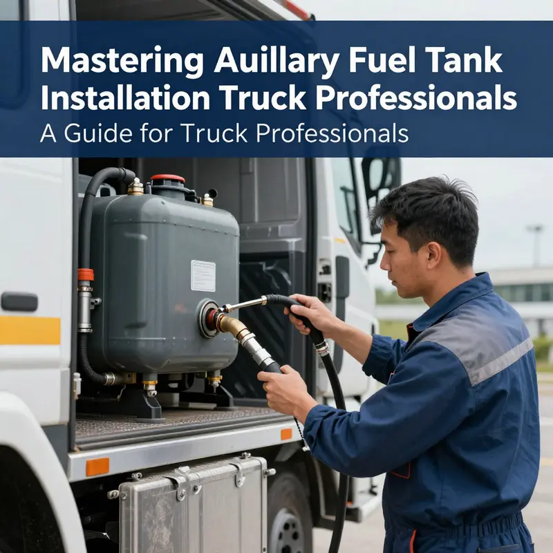
Alongside the plumbing and valves, the physical connections demand exacting workmanship. All joints, hose ends, and fittings must be professional-grade, fuel-resistant, and secured with clamps positioned to avoid loosening due to vibration. The aim is a leak-tight, vibration-tolerant network that behaves predictably under temperature changes, road shock, and long-term exposure to fuel fumes. The installation must also respect local safety regulations and industry standards. In many jurisdictions, this means aligning with recognized codes and standards that govern motor vehicle operation safety and fuel system integrity. A concrete example is the reference to GB 7258, which codifies safety technical conditions for motor vehicles and influences how fuel system modifications are approached in certain markets. This alignment with standards is not a mere checkbox; it is a practical measure that helps prevent catastrophic failures and ensures the modification remains compatible with vehicle inspections and road-worthiness assessments.
Safety and compliance stages begin long before the truck leaves the shop. A systematic leak test is indispensable after assembly. One rigorous method is to fill the auxiliary tank with water and pressurize the system to simulate operating conditions—commonly around 0.3 MPa—looking for bubbles at welds, joints, or fittings. This test detects weak seals, misaligned clamps, or improper transitions that could otherwise fail under fuel pressure or rapid acceleration. If leaks are found, the source must be corrected before any engine operation, and the test repeated until the system remains bubble-free under the test pressure. Beyond leak testing, regulatory approval often governs whether a vehicle may operate with an added fuel tank. In some regions, modifications to the fuel system require prior authorization from a regulatory authority or the local DMV-equivalent body, followed by periodic inspections to verify ongoing safety and emissions compliance. Because rules differ by country and even by local jurisdiction, the responsible shop should stay current with applicable requirements and secure the necessary approvals before the truck is returned to service.
From a professional perspective, the installation is not a DIY sprint but a carefully executed project that benefits from documented qualifications. In jurisdictions where licensing and certification are required, commissioning the work through a shop with appropriate modification qualifications ensures that the modifications are performed to accepted practices. This also provides a traceable record for insurance purposes, which is prudent given the potential risks associated with fuel system modifications. Risk management extends to the filler neck itself. A properly designed check valve or anti-siphon structure helps prevent vapor mixing and siphoning, a measure that protects both the vehicle’s emissions integrity and the safety of personnel during refueling and fueling operations. Insurance considerations may also come into play, with operators seeking coverage that accounts for the added fuel capacity, the risk of leaks, and any consequential damage that could arise from a fuel system modification.
As the project progresses toward completion, attention shifts to integration with the truck’s operational workflow. The solution must not impede routine maintenance. Fuel filter access should remain straightforward, and the routing of lines should not obstruct access to the frame, antennas, or service points. An often-overlooked aspect is grounding and bonding. To mitigate the risk of static electricity—especially in the presence of fuel vapors—the auxiliary tank should be bonded to the chassis with a grounding strap. This practice reduces the likelihood of static discharge occurring during refueling or when transferring fuel and is a straightforward, highly effective safety measure. Grounding also supports compatibility with any aftermarket electronic controllers that monitor fuel levels or manage switching logic, reducing the chance of errant readings caused by electrical noise.
The broader safety framework for auxiliary-fuel installations rests on adherence to recognized standards and the dissemination of maintenance expectations. In the United States and many other markets, standards such as SAE J2478 (Auxiliary Fuel Tanks for Vehicles) provide a detailed foundation for design, construction, installation, and testing. Following these standards helps ensure a robust solution that performs reliably under real-world conditions and that can be shared across fleets with consistent performance expectations. The European context offers parallel guidance through EN 13094, which similarly governs the construction and safety of fuel systems. But standards are not the end of the story; they are the baseline that supports ongoing maintenance and inspection programs. After installation, a schedule for routine checks should be established. Fuel hoses should be inspected for cracking, swelling, or abrasion; clamps should be verified for tightness; and supports should be examined for fatigue or deformation. The vent-system must be checked for proper operation, ensuring that vent lines are clear and flame arrestors are intact. A well-documented maintenance plan reduces the likelihood of unexpected failures and helps the fleet operator retain the reliability that long-range field operations demand.
The narrative above offers a single path to a robust solution, but the practical reality is that every service truck is a distinct machine with its own constraints. The most durable auxiliary-fuel configurations acknowledge site conditions, vehicle duty cycles, and crew workflows. For operators who routinely drive in remote regions or for extended periods away from support facilities, the value of a properly engineered auxiliary tank grows with each mile. It is the difference between a mission that can complete on schedule and one that is forced to pause because the main tank runs dry in an unfriendly environment. To that end, the design philosophy should emphasize not only capacity but resilience: a system that remains functional in heat and cold, that resists corrosion and vibration, and that returns to service quickly after maintenance without requiring a complete reconfiguration.
The practical knowledge gathered from field experiences supports the design choices described here. When selecting a location, operators have reported better outcomes when the auxiliary tank is mounted in a spot that minimizes exposure to exhaust heat and road spray while still providing accessible service points for inspection. The selection of materials, too, has shown that HDPE tanks offer excellent resistance to chemical attack from fuel blends and provide a forgiving surface for impact, whereas stainless steel tanks excel in environments that demand extreme longevity and ease of cleaning. The decision between an automatic switching system and a manual selector hinges on operational tempo and crew preference. In high-volume fleets where technicians may be distracted by multiple tasks, an automatic system reduces cognitive load and ensures the engine draws reliably from the best available source. In smaller shops or in operations with variable pump configurations, a manual system may be preferred for its transparency and simplicity. The key is to document the chosen approach and validate it through testing that mirrors real-world use.
In this chapter you have read about the chain of decisions that begin with concept and end with a road-legal, field-tested installation. A single, well-designed auxiliary-fuel system is not merely a feature; it is a strategic capability that sustains fleet readiness. The design should be described in precise, implementable terms, and the installation should be executed by technicians who understand how every pipe, valve, and bond point contributes to overall safety. The discussion also points toward a practical discipline: integrate a credible internal knowledge base and reference materials so that the team can revisit the rationale behind each design choice. For example, the design principles discussed here intersect with broader concepts of system efficiency and reliability that are covered in resources focused on emergency-service vehicle design and optimization, such as the piece on Design Efficiency in Emergency Services. By examining the interplay between tank placement, line routing, and switching logic, teams can cultivate an approach that respects both performance goals and regulatory boundaries. You can explore these ideas further in related industry discussions that underpin good practice across fleets and service operations.
For readers seeking a robust, authoritative technical reference, SAE J2478 – Auxiliary Fuel Tanks for Vehicles provides comprehensive requirements for design, construction, installation, and testing. This standard, widely referenced in industry practice, anchors the engineering choices described here in a validated framework. You can consult the standard to verify material compatibility, connection methods, and safety margins that apply to your jurisdiction and vehicle class. While the specific regulatory path may vary, the core engineering discipline—clean connections, proper venting, safe switching, and thorough testing—remains universal. The combination of careful design, disciplined installation, and rigorous testing delivers a solution that not only increases range but also preserves safety, reliability, and regulatory compliance for service operations that depend on consistent, uninterrupted performance. External readers and practitioners can cross-check the practical guidance offered in this chapter against the standards and resources that govern institution-wide safety practices.
As a final note, remember that the work described here is not a casual modification. It is a system integration exercise that touches the vehicle’s safety-critical fuel network. The process demands professional expertise, appropriate tools, and a clear understanding of applicable standards and legal requirements. The end result should be a secure, maintainable, and compliant auxiliary-fuel system that extends reach without compromising the safety and performance of the service truck. For operators and fleets seeking to translate theory into practice, the path is to plan meticulously, execute with care, test thoroughly, and maintain diligently. The gains in uptime and mission readiness come when every detail—from valve actuation to venting, from mounting hardware to bonding—works as a cohesive whole. And with that cohesion comes confidence: confidence that the truck can perform its essential service, even when the road ahead is long and fuel is finite.
External resource: SAE J2478 – Auxiliary Fuel Tanks for Vehicles, available at https://www.sae.org/standards/content/j2478_2023/
Between Range and Regulation: Building a Safe, Compliant Auxiliary Fuel Tank on a Service Truck
Extending a service truck’s range with an auxiliary fuel tank is a logical answer to demanding jobs, long shifts, and remote work sites. Yet the decision to add capacity is not just about bigger numbers on a spec sheet. It is a test of discipline, engineering judgment, and, above all, unwavering commitment to safety and regulatory compliance. A well-planned installation can deliver reliable fueling, minimize downtime, and keep the vehicle within the bounds of the law. A sloppy modification, by contrast, can invite fuel leaks, fire hazards, and costly penalties. When safety and compliance become a shared language between design, installation, and operation, the potential for danger or liability dramatically diminishes, and teams can focus on the job at hand rather than the hazard of an improvised fuel system.
Material choices begin the conversation about safety long before the first bolt is tightened. The auxiliary tank must endure vibration, temperature swings, and the corrosive effects of fuel over time. In practice, two materials dominate the market: steel and aluminum. Steel tanks are exceptionally durable and generally cost-effective. They resist impact well and tend to have an established track record in heavy-duty commercial use. The trade-off is weight, which can influence vehicle dynamics, fuel economy, and the mounting system’s required strength. Aluminum tanks, on the other hand, are lighter and resistant to certain forms of corrosion, but their initial cost can be higher and some designs may require more careful attention to structural support and mounting hardware. Regardless of material, corrosion protection, weld integrity, and quality controls during manufacturing must be non-negotiable. A tank that starts strong but cannot weather years of service will fail when it matters most, often at the worst possible moment.
Beyond the tank itself, the mounting system is the first line of defense against failure. A robust design anchors the tank securely to the vehicle chassis, distributing loads evenly and resisting the jolts and shocks of on-road and off-road work. High-strength brackets, reinforced mounting points, and weatherproof, fuel-resistant fasteners are essential. The goal is to prevent movement, even under high-road vibrations or sudden maneuvers, without creating stress concentrations that could crack welds or fatigue mounting points. In the same breath, the system must protect the tank from road debris and environmental exposure. Skid plates, protective coatings, and carefully chosen geometries help the assembly weather harsh environments and extend its service life. The best mounting solutions also consider weight distribution so the vehicle’s handling and braking remain predictable. A poorly placed tank can shift the center of gravity, degrade cornering stability, or reduce ground clearance in critical zones, all of which translate into safety risk.
Venting and labeling are more than bureaucratic checkboxes; they are functional safety features that reduce the risk of dangerous pressure buildup and fuel exposure to personnel. Proper venting prevents pressure accumulation inside the tank, which can lead to venting leaks or, in extreme cases, structural stress. Vent lines must be routed to avoid interference with other systems and have appropriate flame arrestors or filters where required by code. Clear labeling, too, helps prevent dangerous mishandling. The tank’s capacity and the fluid type should be legible, durable, and resistant to fuel fumes. In the context of a service truck, this clarity supports quick, safe decision-making by operators who may be under time pressure or working in less-than-ideal lighting conditions.
Regulatory compliance sits at the heart of mounting an auxiliary fuel tank. In the United States, the regulatory baseline is shaped by the Department of Transportation (DOT) and related safety standards. A critical constraint is the maximum permissible capacity for auxiliary tanks integrated into motor vehicle systems. In many regulatory frameworks, this cap is set at 24 gallons, roughly 100 liters. Exceeding it can trigger penalties, require extensive additional testing, and complicate inspections. It is not just a number; it is a boundary that reflects the balance between practical utility and systemic safety in fuel systems. Implementers must ensure that the auxiliary fuel system is designed and installed in a way that the added capacity does not upset vehicle handling, fuel distribution reliability, or safety margins in the event of a collision or rollover.
No amount of clever engineering can substitute for proper expertise when it comes to modifying a fuel system. Installation should be entrusted to technicians who are not only proficient in automotive systems but also familiar with the regulatory landscape and industry norms. The involvement of certified professionals serves multiple ends: it improves the likelihood of a robust mechanical interface, reduces the chance of fuel leaks, ensures that wiring and electrical integration do not introduce ignition sources, and aligns the project with established codes and inspection regimes. In many jurisdictions, formal approvals are required before a modification can be operated publicly. These approvals often involve a review of the modification plan, a demonstration of leak and pressure testing procedures, and documentation for annual or periodic inspections. When the modification touches fuel delivery and venting, the stakes are higher still, and professional involvement becomes a matter of public safety, not just vehicle performance.
The installation process itself acts as a crucible in which theory becomes practice. A careful sequence begins with a thorough design review that considers the truck’s existing fuel system, the chosen tank’s dimensions, mounting clearance, and how the auxiliary system will interact with the main tank under various operating conditions. A critical design element is the oil pipe layout: the auxiliary tank inlet should connect directly to the main tank’s outlet in a way that minimizes bending stress and reduces the possibility of flow irregularities. The aim is a clean, direct path for fuel that supports consistent pressure and predictable performance. The next phase involves the fuel system modification itself. A high-quality T-connector is installed on the main fuel line to create a branching point for the auxiliary tank. The integration of control valves follows—the solenoid valve provides automatic control of fuel flow from the auxiliary tank, while a manual override switch gives the driver the ability to select between the main and auxiliary supply. This dual-mode control is not merely convenient; it is a safety feature that preserves driver awareness and control in varied operating contexts. All connections must be sealed with professional-grade, fuel-resistant hoses and fittings, and every joint must meet rigorous standards. The entire system should be laid out so that there are no sharp bends or kinks that could impede fuel flow, and every connection must be tested for leaks under conditions that simulate real-world operation. Adherence to standards such as the applicable national vehicle safety code is not optional; it is the bedrock of a safe installation.
As the mechanical work proceeds, safety and compliance take on tangible forms. Sealing tests are carried out to verify integrity under pressure and submersion conditions. A common approach is to fill the system with water and apply pressure to simulate service conditions, frequently up to several tenths of a megapascals. The absence of bubbles or signs of seepage across welds and fittings provides confidence that the installation will not fail under fuel pressure or temperature cycling. Electrical wiring and grounding are treated with particular care. The entire system must be electrically isolated from the vehicle’s ignition system to prevent sparks near any fuel vapor—an essential precaution given the inherent flammability of the cargo. This attention to electrical safety extends to ground straps, shielding, and careful routing of wires away from hot exhaust components and moving parts. In all, the goal is a fault-tolerant interface between the auxiliary tank and the main fueling system that minimizes the risk of leak, spark, or mechanical fatigue.
Another layer of safety arises from anti-siphon considerations and vapor management. Installing a check valve or an anti-siphon structure at the fuel filler neck helps prevent unintended siphoning and reduces the risk of vapor mixing in enclosed spaces. Such measures are not merely about preventing loss of product; they are about safeguarding occupants and maintaining regulatory compliance for emissions and fuel handling. In service trucks, where vehicles may operate in cold, dusty, or humid environments, the robustness of seals and connectors becomes a practical concern. The system must tolerate thermal expansion and contraction, fuel temperature fluctuations, and exposure to water or cleaning agents without compromising safety. Regular maintenance and timely replacement of worn components are essential to maintaining these safety margins.
Alongside safety, the installation must address broader risk management considerations. Insurance considerations can shift after a modification that introduces a new fuel tank. It is prudent to engage with insurers to ensure that the modification is covered and that terms reflect the new risk profile. Documentation is indispensable here: keep records of tank specifications, mounting hardware, venting paths, testing results, and approvals. This documentation not only supports compliance audits; it also provides a practical reference during maintenance or in the event of a claim.
Maintenance and inspections form an ongoing discipline that extends the life of the auxiliary fuel system and reinforces safety. The system should be included in the routine inspection cadence for the vehicle, with specific emphasis on bracket integrity, mounting hardware wear, leakage around seals, vent line integrity, and electrical connections. Corrosion checks are particularly important for steel tanks, while aluminum tanks should be checked for any signs of cracking or fatigue at welds and along the mounting interface. Any signs of movement, unusual noise, or abnormal fuel odor should trigger a pause in service to allow a qualified technician to reevaluate the installation. The objective is to create a culture of proactive upkeep rather than reactive repairs, recognizing that a well-maintained system reduces unplanned downtimes and the risk of hazardous events.
Internal knowledge sharing among maintenance teams can be supported by targeted training. For those responsible for evolving service fleets, staying current with best practices in fuel system safety is essential. Practical, scenario-based training that covers design choices, leak testing methodologies, electrical isolation, and regulatory expectations helps teams make sound decisions when modifications are contemplated or when troubleshooting arises. For guidance on maintaining safety-focused practices, see fire-truck-maintenance-training-importance. This resource emphasizes the broader context of upkeep, training, and discipline that should permeate any major modification project and reinforces that safety is not a checkbox but a continuous practice. The goal is to embed a mindset where every team member understands the stakes and contributes to building a safer, more dependable vehicle.
It is also important to anchor the discussion in authoritative guidance. For baseline regulatory references and official standards, consult the DOT Fuel Systems guidance. This external resource provides formal criteria and updates that inform sound engineering decisions and installation practices. Keeping up with these standards helps ensure that the system remains compliant as rules evolve and as new safety technologies emerge. When the work is complete, the vehicle should be prepared for the kinds of inspections that operators may encounter at road checks, maintenance facilities, or during fleet audits. A well-documented, thoroughly tested installation that demonstrates a clear demonstration of safety measures—proper venting, secure mounting, leak-free joints, electrical isolation, and driver-accessible control—will fare far better under scrutiny.
In sum, adding an auxiliary fuel tank to a service truck is a decision that integrates physics, safety science, regulatory realities, and practical operations. The most successful installations are those that treat safety and compliance as a shared mission rather than an afterthought. They begin with solid design choices and continue through meticulous installation, rigorous testing, and disciplined maintenance. They respect boundary conditions set by the governing authorities—such as the 24-gallon cap that governs integrated auxiliary tanks in many jurisdictions—while providing the practical benefits that fleets seek in demanding service environments. When approached with care, the result is a system that extends range without compromising safety, reliability, or legal standing, and that supports the people who rely on these trucks to perform critical work in challenging conditions. For operators and technicians, the result is not just a more capable vehicle; it is a safer, more accountable system that stands up to the rigors of daily duty and regulatory expectation. External resources and the collective knowledge of the profession reinforce that the path to safe, compliant fuel systems is continuous learning, rigorous testing, and disciplined execution rather than a one-time alteration. External resource: DOT Fuel Systems: https://www.transportation.gov/vehicle-safety/fuel-systems
Final thoughts
Successfully mounting an auxiliary fuel tank on a service truck involves not just technical skill, but also a thorough understanding of safety protocols and compliance regulations. By carefully planning the system design, executing precise modifications, and adhering to necessary safety regulations, transport professionals can significantly enhance the operational efficiency of their trucks. This extended tank capability not only optimizes downtime but also drives long-term savings—essential for any fleet manager or truck driver focused on performance.